As promised in my previous post, I have uploaded the gerbers, schematic, and bill of materials for the 3D Printer Stellaris Launchpad Booster Pack. I have also uploaded the firmware to Github for others to use. The firmware is released under a GPLV3 license and is available here: http://www.github.com/mroy/stellarap
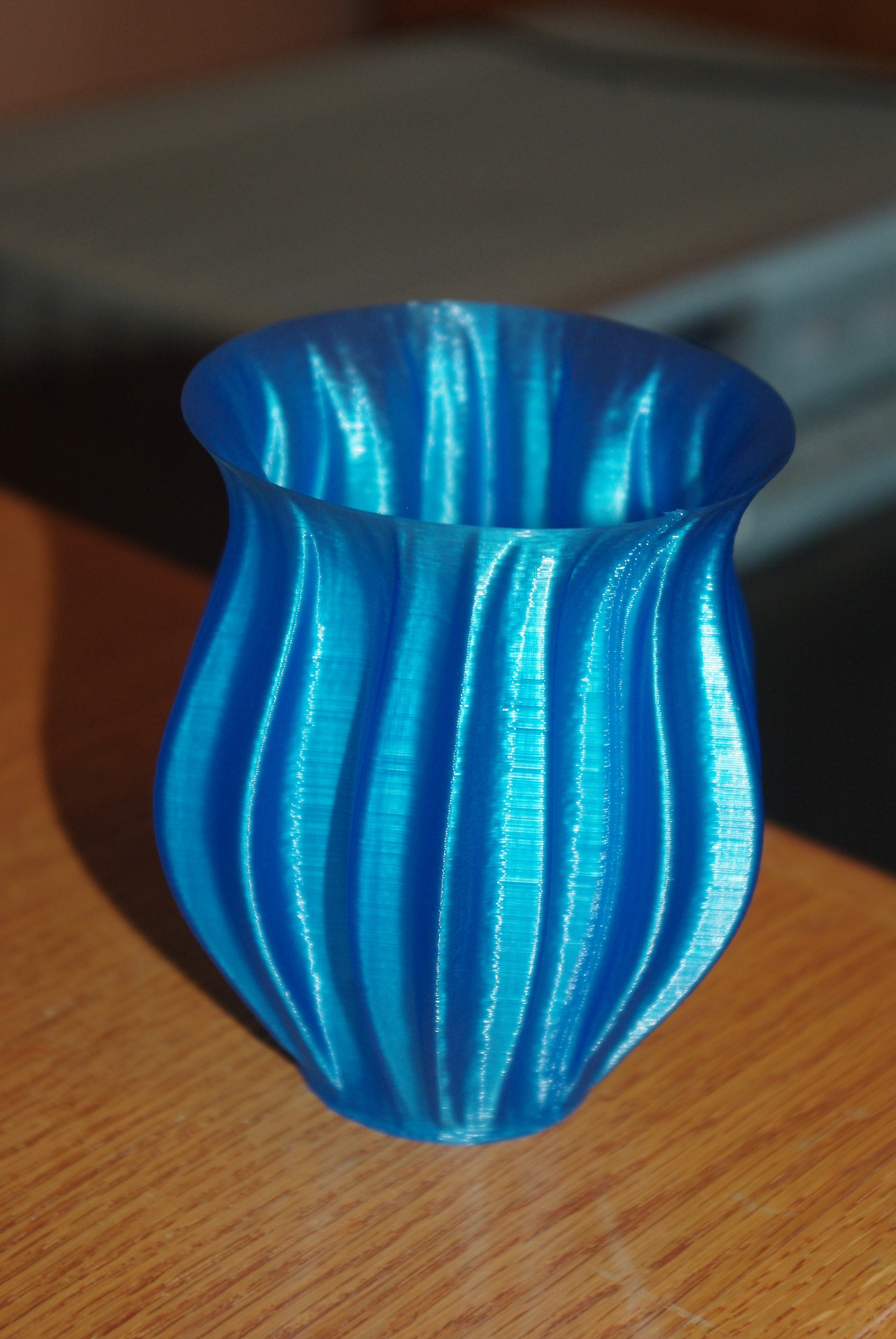
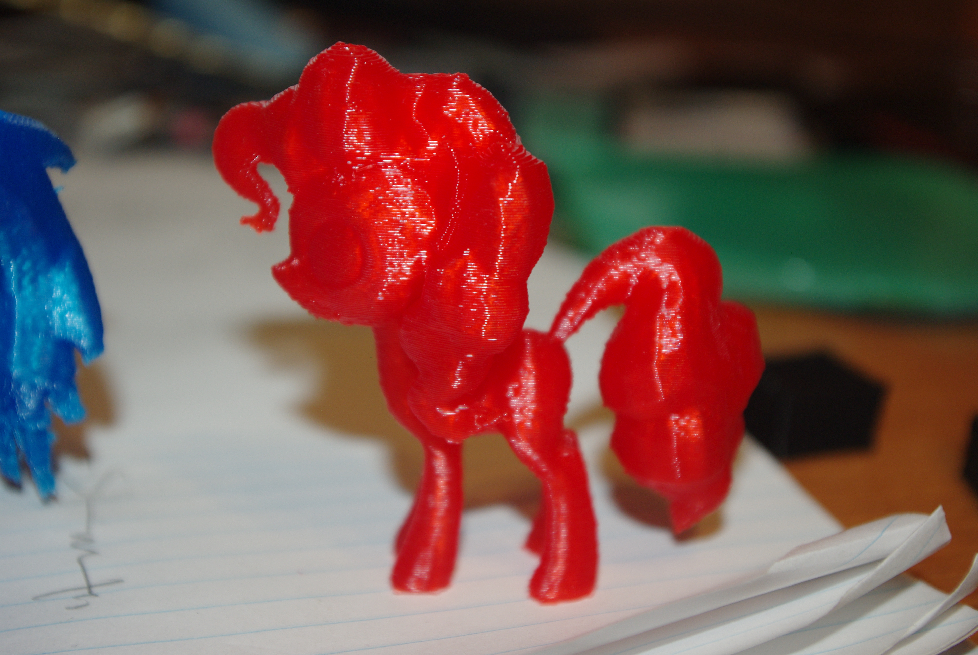
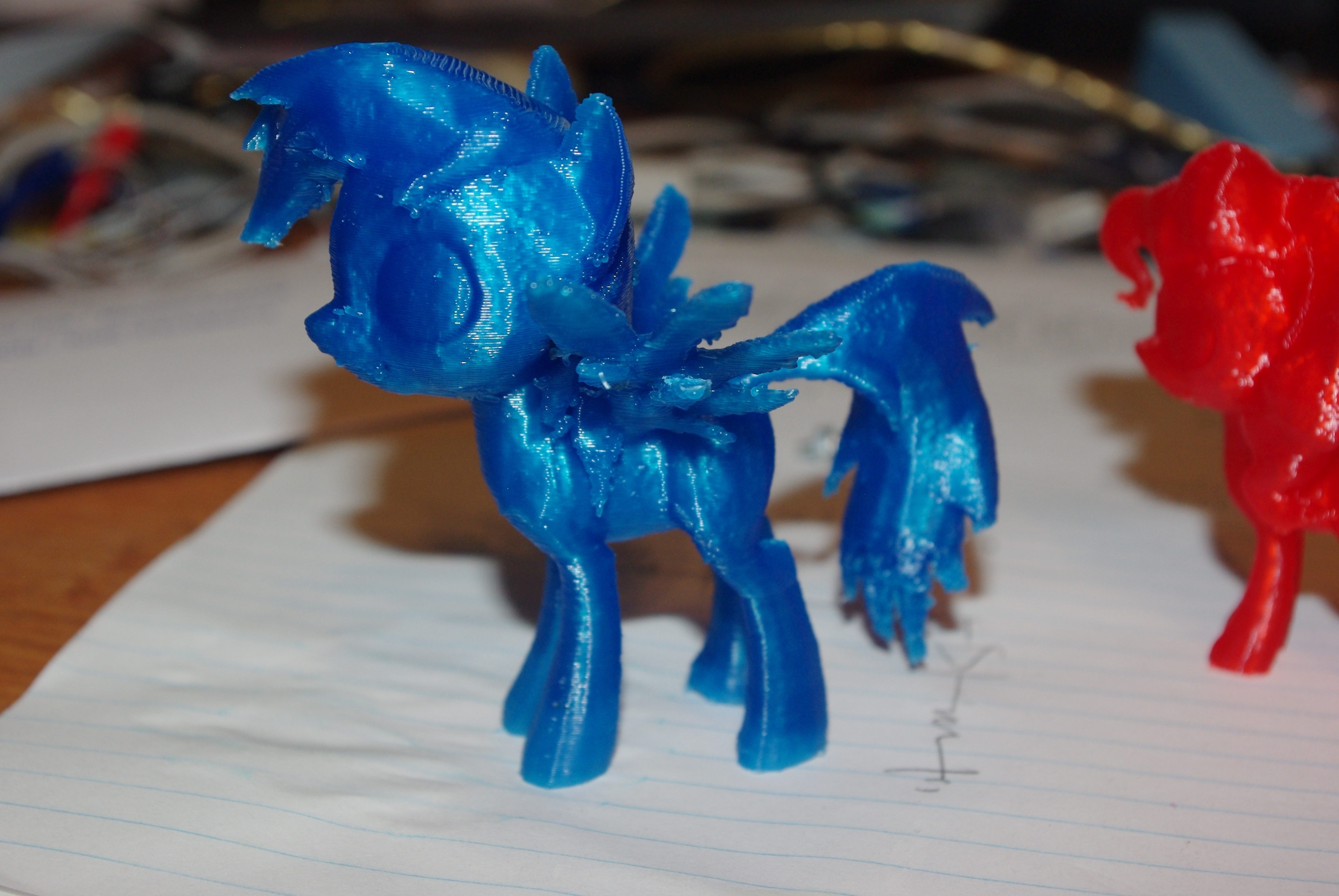
Above you can see a couple of prints that I have done on my printer. The first is a scripted vase and the second two are a couple of My Little Pony models (Pinky Pie and Rainbow Dash). All of the above models are from thingiverse, a great source for printables. Note that the pony models were fairly time consuming because of the complex supports required for the tail, hair and wings.
Hardware
The RAR file above includes the following files:
- stepper.apr – Aperature Library for GERBERS (you probably wont need this)
- stepper.GBL – Bottom Layer Gerber
- stepper.GBO – Bottom Layer Silkscreen
- stepper.GBP – Bottom Layer Solder Paste
- stepper.GBS – Bottom Layer Solder Mask
- stepper.GM1 – Mechanical Layer 1 (connector/component outlines)
- stepper.GM13 – Mechanical Layer 13 (connector/component outlines)
- stepper.GM15 – Mechanical Layer 15 (component courtyards)
- stepper.GTL – Top Layer Gerber
- stepper.GTO – Top Layer Silkscreen
- stepper.GTP – Top Layer Solder Paste
- stepper.GTS – Top Layer Solder Mask
- stepper_round_holes.drl – NC Drill file
Note that I forgot to include an outline on one of the mechanical layers, but it shouldnt be too hard to figure out from the outline of the polygons on the top/bottom layers.
Also note that this board design is designed for DIY PCBs. There are no hidden vias which makes it possible to stitch vias with a piece of wire and not having to worry about putting an IC on top of a solder blob. Also, note that the driver ICs do not have the greatest thermal pads because I was restricted to not using any thermal vias beneath them and since I was also soldering this by hand, I had to include a thermal relief connection to the pad beneath each driver IC. This allows them to be soldered by tinning the bottom pad of the chip, tinning the pad beneath the chip, applying lots of flux, and then heating up the entire thermal pad with a soldering iron tip while the chip is on the pad. This seems to work OK, but I have also added a large chipset heatsink from an old mother board that sits on top of all four driver chips with a bit of thermal compound. The heatsinking seems to work fine for keeping them cool at the currents that I am running them.
If you are going to have this board manufactured properly, I would highly suggest adding thermal vias beneath the driver ICs and removing the thermal reliefs. This should eliminate the need for a heatsink entirely. Also use 2oz copper if you can.
The hardware also includes a 3.3V regulator that is meant to provide power to the Launchpad. For this reason, you should remove the jumper on the LaunchPad that connects the USB power to the onboard regulator and make sure that the switch is set for device power.
Notes on the Bill of Materials:
The BOM lists the driver chip as A4984, but the A4982 should be used instead as it has better microstepping.
The connectors J2,J3,J6,J7,J8 are Molex right angle .1″ pitch connectors such as the 0705550004 (WM4167-ND on DigiKey), but in a pinch any 0.1″ pitch connector should be usable.
C12 and C23 are 100uF aluminum electrolytic capacitors. Anything ~100uF or larger that seems to fit in the hole spacing and has at least a 12V voltage rating should be suitable for these.
Also, take a look at the schematic and you will need to tune the current with two resistors for each stepper. Do not run them with too much current or you will risk overheating your steppers. I think I am running mine at around 800 – 1000mA. I have the extruder and z axis a bit higher than the X and Y. Also, in the firmware I may have switched around which axis is which for the drivers on the board.
Firmware
As mentioned in the summary, the firmware is available here:
http://www.github.com/mroy/stellarap
The README.md file from the repository is copied here for your reference:
Stellarap http://www.stellarcore.com/ This is a firmware for a stellaris launchpad based controller for a 3D printer.
License: The Stellarap code is licensed under the GNU GENERAL PUBLIC LICENSE, Version 3, 29 June 2007. The license is available here http://www.gnu.org/licenses/gpl-3.0.txt and is also provided in the accompanying LICENSE file. This License MUST be included in all distributed versions of this code. All of this software is provided AS-IS with no implied warranty or liability under sections 15, and 16 of the GPL V3. If your printer burns down your house, it’s not my fault.
- Disclaimer of Warranty. THERE IS NO WARRANTY FOR THE PROGRAM, TO THE EXTENT PERMITTED BY APPLICABLE LAW. EXCEPT WHEN OTHERWISE STATED IN WRITING THE COPYRIGHT HOLDERS AND/OR OTHER PARTIES PROVIDE THE PROGRAM “AS IS” WITHOUT WARRANTY OF ANY KIND, EITHER EXPRESSED OR IMPLIED, INCLUDING, BUT NOT LIMITED TO, THE IMPLIED WARRANTIES OF MERCHANTABILITY AND FITNESS FOR A PARTICULAR PURPOSE. THE ENTIRE RISK AS TO THE QUALITY AND PERFORMANCE OF THE PROGRAM IS WITH YOU. SHOULD THE PROGRAM PROVE DEFECTIVE, YOU ASSUME THE COST OF ALL NECESSARY SERVICING, REPAIR OR CORRECTION.
- Limitation of Liability. IN NO EVENT UNLESS REQUIRED BY APPLICABLE LAW OR AGREED TO IN WRITING WILL ANY COPYRIGHT HOLDER, OR ANY OTHER PARTY WHO MODIFIES AND/OR CONVEYS THE PROGRAM AS PERMITTED ABOVE, BE LIABLE TO YOU FOR DAMAGES, INCLUDING ANY GENERAL, SPECIAL, INCIDENTAL OR CONSEQUENTIAL DAMAGES ARISING OUT OF THE USE OR INABILITY TO USE THE PROGRAM (INCLUDING BUT NOT LIMITED TO LOSS OF DATA OR DATA BEING RENDERED INACCURATE OR LOSSES SUSTAINED BY YOU OR THIRD PARTIES OR A FAILURE OF THE PROGRAM TO OPERATE WITH ANY OTHER PROGRAMS), EVEN IF SUCH HOLDER OR OTHER PARTY HAS BEEN ADVISED OF THE POSSIBILITY OF SUCH DAMAGES.
Pre-requisites:
ARM Cortex-M4 toolchain such as: GCC Arm Embedded https://launchpad.net/gcc-arm-embedded CodeSourcery Lite GCC EABI for ARM http://www.mentor.com/embedded-software/sourcery-tools/sourcery-codebench/editions/lite
Stellarisware Software Package (since renamed to TivaWare): This software library includes functions and libraries for many of the on-board peripherals used in the chip.
The library has also been compiled and optimized in the ROM that is available on the chip itself, meaning that library calls to TivaWare functions cost no program memory. It also includes some special initialization stuff that is needed for the particular ARM core in the chip. http://www.ti.com/tool/sw-tm4cC Libraries I have used my own compiled version of Newlib to provide libc.a and libm.a which provides some standard C functions as well as math functions. It is likely that you will be able to find a pre-compiled version of newlib or even use the version that is included with the toolchain (above). http://sourceware.org/newlibhttp://eehusky.wordpress.com/2012/12/17/using-gcc-with-the-ti-stellaris-launchpad-newlib/
Recommended Software: OpenOCD compiled with support for the TI Link This is a great software that I use to debug with the Stellaris Launchpad. It allows you to use the built in TI Link that is on the development board with the GDB included in the GCC toolchain. Instructions for building/using the Stellaris Launchpad with OpenOCD are here:http://processors.wiki.ti.com/index.php/Stellaris_Launchpad_with_OpenOCD_and_Linux
Build Instructions: Set your path to include your compiler toolchain.
$make clean
$make
Flash/Debug Instructions: Start OpenOCD with the stellaris connected through the development USB connector. $./openocd & $arm-none-eabi-gdb main.axf target extended-remote :3333 monitor reset halt load monitor reset init run
Acknowledgements: Great thanks to the folks in irc.freenode.net/#reprap for the help to understand 3D printing and for helping me to understand what the firmware should be doing. Special thanks to Kliment for his help explaining the Marlin firmware, which my firmware may bare a striking resemblance to.
A brief description of the files included in the repository:
- 104JL1A REV NONE (R-T Table).xls – this is an Excel file for one of the thermistors I have used. This was used to generate a table in the firmware
- B57540.pdf – this is a PDF datasheet for another thermistor that I have used.
- B57540G0104F000.xls another excel for the second thermistor (I should probably remove these from the repository, but maybe later)
- LICENSE – a copy of the GPLV3
- LM4F.ld – A public domain linker script written by Elias Onal for Thumb2 Newlib Toolchain projects
- LM4F_startup.c – Some startup code for the processor. Written by Mauro Scomparin (license included in the source)
- Makefile – a makefile for compiling the project based on one from Mauro Scomparin (license included). May need slight modification for paths to stellarisware and newlib binaries.
- createTemperatureLookup.py – A python script based off of http://hydraraptor.blogspot.com/2007/10/measuring-temperature-easy-way.html Modified to generate a table in the form that my firmware uses.
- delay.c / delay.h – A method to provide accurate delays based on a timer ISR.
- endstops.c / endstops.h – Methods to debounce and handle an endstop ISR.
- heaters.c / heaters.c – Methods to PI control the heatbed and hotend heaters. heaters.c includes the thermistor tables to use as well as the proportional and integral gain constants. Note that there currently is no derivative gain, but this has very little effect on the heaters which are already incredibly slow to react to changes, so there should be no real need for it. PI gains have been experimentally found to work reasonably well with my current setup. Your milage may vary and you will likely want to play with these a bit.
- interpreter.c / interpreter.h – This is where the GCODE is interpreted. Current implemented commands include: G0,G1,G4,G21,G22,G28,G90,G91,G92,M0,M1,M17,M18,M84,M82,M83,M104,M140,M105,M110,M112,M999 (heater test). It also supports the N line number and checksums that are standard in most firmwares.
- planner.c/planner.h – This is where the magic of block planning happens. When the interpreter needs the machine to move, it calls the planner with coordinates and the planner translates this into a block for the queue with steps/directions. Planner.c includes the axis steps/mm and maximum speeds. Also includes a special routine for homing.
- stepper_control.c / stepper_control.h – This is where the stepper control is done and the block queue is processed by a timer ISR. stepper_control.h contains block_queue_size, max step rate, min step rate, maximum accelerations, and maximum jerk settings. Also includes axis settings that control the direction of each axis stepper motor.
- main.c – The main program. It initializes a bunch of stuff and then starts an infinite loop waiting for commands. Note that all commands are expected to come in via the debug UART at this time. In the future it would be good to update the firmware to use it’s own USB connection for this.
Finally, I would like to mention that if you would like to try out the firmware without actually building a machine and you have a Stellaris Launchpad kicking around, you can build and program the firmware and it will emulate a printer with the three RGB led, each colour corresponding to the X,Y, or Z axis.
Would you be willing to provide a more in-depth explanation of the compiling process on a Linux platform for the amateur Linux users out there? I’ve run into a couple snags trying to implement your firmware and haven’t quite figured out why.
Sure. I will try to post some instructions on how to setup the tool chain and compile on a fresh Linux virtual machine in the next day or so.
Cheers and thanks for your interest.
Hi, i really like your work here! .One thing i don’t understand is that how is the 3D image being sent to the controller. Is there any user interface? and also another thing i would like to that is there an Energia version of the code possible?
The controller accepts standard G-code instructions. When connected to a computer via USB, the launchpad appears as a CDC serial device (virtual com-port). From here, you can send raw commands via a serial terminal, or you can use an application like Pronterface. Pronterface basically acts as a nice interface for the printer and sends it commands as needed. To generate the actual G-code, you need to use a slicer program such as Slic3r. The slicer program basically takes a 3D model (usual an .STL file which you can generate from Google Sketchup, Blender, OpenSCAD, Autodesk Inventor, or countless other CAD/modeling program), and figures out how to make that object using the printer.
Hope that helps to explain it! As for Energia, that is the first I’ve heard of that project and so my code is likely not compatible. Looking at the Energia website, it seems that it is meant primarily for the MSP430 LaunchPad, whereas my code is meant to run on the Arm Cortex M4 Tiva LaunchPad (formerly Stellaris Launchpad). I dont know that the MSP430 would be fast enough to properly control a 3D printer. The fastest MSP430 seems to be only 25MHz whereas the Tiva chip used in my project is an 80MHz 32-bit processor with floating point unit that I make quite heavy use of. Note that the Tiva Launchpad is only $12.99 on the TI website! But you will need to build a shield to connect the stepper motors and heaters as I used them in my code.
In the future (maybe this year, maybe next?) I plan on developing my own open hardware controller board for 3D printers using the TiVa controller. There are lots of these boards out there already, but most (all?) of the ones I have seen so far are based on Atmel processors (Arduino). I think it’s great to have some diversity and it’s a fun challenge for me to design and build them myself.
Cheers, and good luck!
Can You provide compiled .bin version for old LM4F120H5QR board? I’d tried to compile it but I can’t comunicate with programed board, I’m getting timeouts.
Hello Kaczy,
I’m really busy this week but I will try to post a compiled binary when I can. Also, make sure that when you are connecting to the programmed board that you are connecting through the programming USB connector. My firmware does not implement USB natively to use the other USB port, so I just do everything through the programming port. Are you running the board with GDB? Can you tell where it is getting stuck? Any debugging info or bugfixes that you can provide would be greatly appreciated.
Cheers!
Hello Kaczy,
I justed added some compiled binaries to the github. Please give them a try and see if they work for you. The files are main.axf and main.bin
Let me know if you still have problems
It took a bit but I finally got the code to compile in CCS with all the changes that they’ve made to the StellarisWare/TivaWare. I tried to connect via PronterFace but it just says Connecting indefinitely. I checked to make sure that I am in fact getting a connection via the UART by adding a simple bit of code during the Interpreter.C right after the UART is initialized to print to the Port. Connecting via PuTTY I can see the text when the controller boots. I was wondering if you could upload the pre-compiled version of the code again to GitHub, or provide some insight to what I may be missing. (LM4F120HQ5R LaunchPad). Thanks.
Hi Blair! I am away from my computer this week but next Thursday I’ll see what I can do. Try manually entering in putty some gcode like M105 to see if it responds. Aside from that maybe try debugging with openocd and gdb.
I could not find any binaries at Github?
What tool do you use to load the binary into the tvia?
Hello,
The tool that I use to load the firmware is the OpenOCD debugger using the built in USB TI-Link provided on the launchpad. The post here: http://www.stellarcore.com/?p=156 details this process.
It does look like the binary is missing from the github. When I get home from work today I will double check and make sure to add the binary to github.
Still having trouble with my Energia build not working correctly.
Its printing but taller objects get shifted in the X and the Y 0.5 mm at random times.
I maybe loosing some of my steps.
Can you send me a .hex file of your compiled code that I can load and try out.
I don’t think its my hardware.
Bill Seiler
Hi Bill,
I just added the binary files main.bin and main.axf to the github repo.
main.axf is built with debugging symbols so you should be able to use it with GDB if needed.
Let me know if they work for you!
Regards,
Mark
Thanks I will go get the binarys.
I think I fixed the slipping problem by changing the MOTOR_ACCEL_RATE from 100000 to 10000.
I still have a problem with the Z axis. The Z axis stops after moving about 2 -3 mm. It never does it when printing.
When I do Home Z it stops . Or if I tell it to move more than 5 mm with a G1 gcode.
Interesting. I know that I had a similar problem with an early version that I was using. The problem occurred when too many steps are required for a single block (ie it overflows the data type or something like that).
To fix this, I updated it somewhere so that it would just split large moves into multiple blocks, but this gave the side effect that for large moves it would move a bit, then stop, then move some more to complete the move. I never bothered to change the planner to eliminate the deceleration/acceleration between these split blocks because large Z-moves are uncommon during the print and when jogging or homing, I dont mind if it stops/starts.
It is possible that maybe you’re hitting this same issue but with shorter move if you have more steps per mm with your z-axis than I do. I looked quickly at the code to see if I could find where it does this, but was having some trouble finding the exact spot. I suggest that you enable some of the printfs that I have in the code and recompile so that you can get some details on the blocks that are failing. If you track down a bug, please let me know or do a pull request on Github.
Thanks!
I found the Z problem. It was my stepper drivers. I am using TI DRV8825 Pololu boards. I had the mode set for 32 micro steps. I had the axis_steps_per_mm for Z set to 8000. Something must have been overflowing. I switched back to 16 micro steps in the Pololu’s and axis_steps_per_mm for Z set to 4000. Printing good now. Now I need to fix the bug where to code hangs up after the print is finished. Code waiting for num_blocks to go to zero. The Timer ISR should decrement num_blocks. Tried to debug and step through the code. Still problem with Code Composer Debuger. When I hit a break point and stop or single step. I end up in an infinite while(1) loop in the bad ISR handler.
Cool… I have a couple Stelleris launch pads sitting around and beginning a repstrap / DIY CNC.
You want some of my blank PCB’s I got from China? You stuff with your parts.
Dear Mark,
based on your article, I’ve developped reprap control board, containing stellaris launchpad, A4988 drivers and MCP23017 expander for step size and led control.
I wished to port your firmware to my control board and so I did. As the host software I am using printrun/pronterface and all the manual functions work well, including temperature measuring and setting, XYZ axis movement, homing etc., dimensions matches as well.
BUT I’am facing problems with actual printing. After loading .gcode file, printer homes all axes and just halts, sometimes it makes few instructions and then halts. It looks like there is something wrong with the interpreter. Don’t you ever had similar problems, or could you advice me what should I do?
It is interesting, that If I click pause and resume at pronterface (when the printer is stucked), the communications goes on and then breaks definitely at Buffer Overflow.
I’ve posted the commented command log to pastebin: http://pastebin.com/MuXnqM4M
Thank you in advance for any help. I could send you some info about my board if you’re interested.
Lukas
Hi Lukas,
I’ve uploaded a sample gcode file that I have used recently that printed well. I suggest that you give this one a try and also use the GDB debugger to try and track down the source of your problems. Try halting the processor when it is stuck and see where in the code it is executing. One thing to look for is whether the timer interrupt routine in stepper_control.c is blocking for some reason or taking too long. This routine currently masks all interrupts and so if it takes longer than the time for a character to come in by serial, then it may cause serial data to be missed. If this is the case, then you could experiment with leaving interrupts running during the timer_isr or maybe just masking everything but the serial interrupt.
Please keep me updated on your results and also I would be very interested in seeing your control board schematics/layout. I might even be interested in making one of my own. I have been planning on designing my own control board for some time but have not gotten to it just yet. Did you order PCBs or make your own?
Thank you for your answer! I certainly try your code and keep you updated as soon as possible. Unfortunately I’m out till sunday so I’ll prepare all the documents and send them to you as soon as I am back.
I tried to design fine PCB so I used two layers with vias and very small clearance which I would not be able to make at home so I ordered it from near manufacturer. Actually, it was at least twice more expensive than any control board from ebay but I wanted to become more familiar with stellaris, It was a challenge for me and I was glad that it works 🙂
Here is photo of the board:
http://ltech.cz/wp-content/uploads/2015/08/20150820_0007_01.jpg
There are just few blocking caps, electrolytes and a port expander at the bottom side