Overview
This project uses RGB LEDs to create a clock face. Each hand is assigned a colour and as the hands overlap on the face of the clock it mixes the colours.
The clock uses a single AA battery to power the display which is boosted to 5 volts with a switching mode power supply. The power supply should be able to use any AA battery that is at 0.7 volts or higher, which means that it should still work fine with AA batteries that may be “dead” when used in other devices.
The heart of the clock is a DS1307 realtime clock with a CR2032 coin cell battery backup. The battery should be sufficient to keep the time for at least a couple of years.
Please see this youtube video which shows my working clock prototype:
Design
The clock was designed with EagleCAD, and the schematic and parts layouts are below:

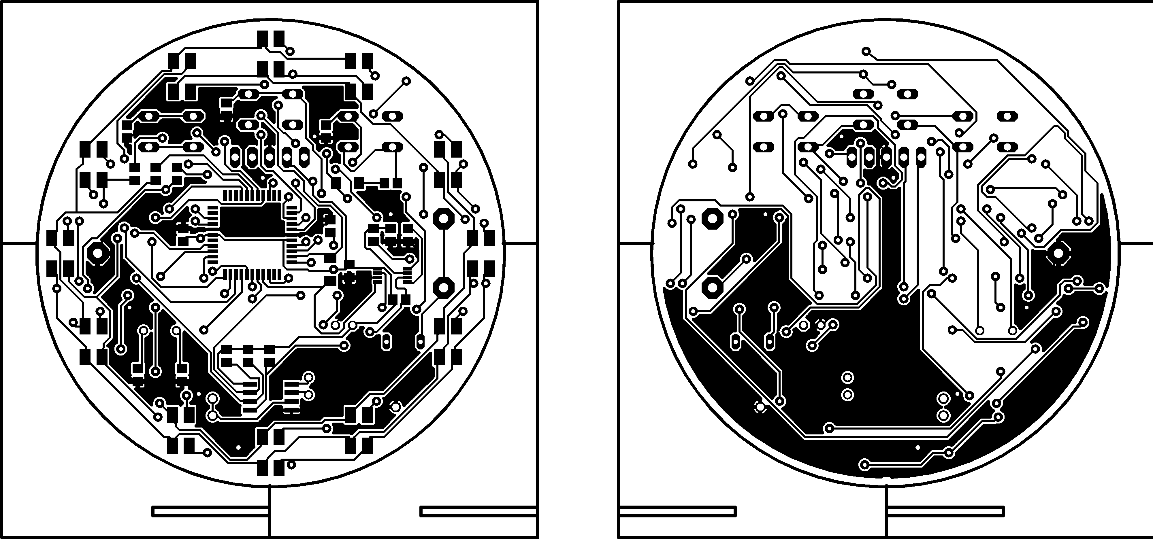
A black/white version of just the copper layers is posted here so that you can make your own. It is printed at 300dpi so make sure that when you print it that its done at the right scale:
The above are already mirrored so that you should be able to print them out directly onto toner transfer paper and transfer it to copper to be etched. Once etched, just cut out the circle from the PCB and if you can, you can try and scavenge the outline to make a bit of a stand for it.
Hardware
The main components of the clock are listed below with links to their datasheets:
- PIC16F877A microcontroller
- MAX1675 Switching Mode Power Supply
- DS1307N Real Time Clock
- LATB_T686_OBS Red,Green,Blue LED
For a complete bill of materials with digikey part numbers and approximate prices, click here
Firmware
The firmware was written in C, compiled with the ccs compiler. I’ve posted a copy of the source code for you to look at below, and you can also download the raw source file here, and the compiled hex file here.
The only thing that I should note is that this software was written for the first prototype which has some minor hardware differences and may need some small changes such as the mappings of the buttons to make it function properly. Once I’ve built the latest version of the hardware I’ll post the updated software. If you build the hardware before I’ve posted revised software and are having problems, feel free to contact me and I’ll do my best to assist with getting you working firmware.
#include  <16F877a.h>
#fuses XT, NOWDT, NOPROTECT, NOBROWNOUT, NOCPD, NOPUT
#use delay(clock=1M) // value based on crystal

#define DS1307_SDA  PIN_B7
#define DS1307_SCL  PIN_B6

#define H_BUTTON PIN_B3
#define M_BUTTON PIN_B1
#define S_BUTTON PIN_B2

#define RED PIN_D0
#define BLUE PIN_D1
#define GREEN PIN_D2

#define LED1 PIN_A1
#define LED2 PIN_A2
#define LED3 PIN_A3
#define LED4 PIN_A0
#define LED5 PIN_A5
#define LED6 PIN_E0
#define LED7 PIN_D7
#define LED8 PIN_D6

#define LED9 PIN_D5
#define LED10 PIN_D3
#define LED11 PIN_D4
#define LED12 PIN_E1

#use i2c(master, sda=DS1307_SDA, scl=DS1307_SCL, Fast)

boolean button_2 = true;
boolean reset=false;
int8 h,m,s;
int8 lastH,lastM,lastS;
int8 updateTimer=0;

char ledMap[12] =     {LED1, LED2, LED3, LED4, LED5, LED6, LED7, LED8, LED9, LED10,LED11,LED12};
int16 ledColour[12] = {0x800,0x810,0x880,0x080,0x028,0x008,0x108,0x228,0x000,0x000,0x000,0x000};
int16 colourWheel[12] = {0x800,0x810,0x880,0x080,0x028,0x008,0x108,0x228,0x000,0x000,0x000,0x000};
int16 hbutton;
int16 mbutton;
int16 sbutton;
boolean colourWheelInit = true;

BYTE bcd2hex(BYTE bcd)
{
  return (bcd & 0x0F) + (bcd >> 4)*10;

}

BYTE hex2bcd(BYTE hex )
{
  return ((hex / 10) < < 4) | (hex % 10);

}

//==========================
// initial DS1307
//==========================
void init_DS1307()
{
  output_float(DS1307_SCL);
  output_float(DS1307_SDA);

}
//==========================
// write data one byte to
// DS1307
//==========================
void write_DS1307(byte address, BYTE data)

{
  short int status;
  i2c_start();
  i2c_write(0xd0);
  i2c_write(address);
  i2c_write(data);
  i2c_stop();

}

//==========================
// read data one byte from DS1307
//==========================
BYTE read_DS1307(byte address)
{
  BYTE data;
  i2c_start();
  i2c_write(0xd0);
  i2c_write(address);
  i2c_start();
  i2c_write(0xd1);
  data=i2c_read(0);
  i2c_stop();

  return(data);
}

void get_time_DS1307()
{
  i2c_start();
  i2c_write(0xd0);
  i2c_write(0x00);
  i2c_start();
  i2c_write(0xd1);
  s=bcd2hex(i2c_read());
  m=bcd2hex(i2c_read());
  h=bcd2hex(0x3F&i2c_read(0));
  i2c_stop();

}

#INT_EXT
void wake_up()
{
  int i;

  disable_interrupts(INT_EXT);

  s=bcd2hex(read_DS1307(0x00));
  m=bcd2hex(read_DS1307(0x01));
  lastM=0xFF; lastH=0xFF;
  lastS=s;
  colourWheelInit = true;
  for (i=0;i<12;i++)

    ledColour[i]=(int16)(colourWheel[i]);

  setup_timer_1(T1_INTERNAL);
  enable_interrupts(INT_TIMER1);
  reset=true;

}

#INT_TIMER1
void button_poll()
{
  int i,ColourIndex,ColourValue;
  int16 tmp;

  if (input(H_BUTTON) == 0)
    hbutton=((int16)hbutton+(int16)1);
  else

    hbutton=0;

  if (input(M_BUTTON) == 0)
    mbutton++;
  else

    mbutton=0;

  if (input(S_BUTTON) == 0)
    sbutton++;
  else

    sbutton=0;

  if (!colourWheelInit || (s - lastS) >= 4)

  {

  if (s-lastS >= 4)
  {
    for (i=0;i<12;i++)

      ledColour[i]=0;
    colourWheelInit=false;
    lastS = 0xFF;
  }

  if (updateTimer==6 || lastS == 0xFF)

  {
    if (s!=lastS)
    {
      ColourIndex = (s / 5) % 12;
      ColourValue = s % 5;
      ledColour[(ColourIndex+11)%12] &= 0xFF0;
      ledColour[ColourIndex]|=((int16)(5-ColourValue));
      ledColour[(ColourIndex+1)%12]|=((int16)(ColourValue));

      if (s0;i--)
      ledColour[i]=ledColour[i-1];
    ledColour[0]=tmp;
  }

  if (hbutton > mbutton && hbutton > sbutton)
  {
    if (mbutton == 2 && sbutton == 0)

    {
      h=(h+11)%12;
      write_ds1307(0x02,hex2bcd(h));
    } else if (sbutton == 2 && mbutton == 0)

    {
      h=(h+1)%12;
      write_ds1307(0x02,hex2bcd(h));
    }

    lastS=0xFF; lastM=0xFF; lastH=0xFF;
  }

  if (mbutton > hbutton && mbutton > sbutton)

  {
    if (hbutton == 2 && sbutton == 0)
    {

      m=(m+59)%60;
      write_ds1307(0x01,hex2bcd(m));
    } else if (sbutton == 2 && hbutton == 0)

    {
      m=(m+1)%60;
      write_ds1307(0x01,hex2bcd(m));
    }

    lastS=0xFF; lastM=0xFF; lastH=0xFF;
  }

  if (sbutton > hbutton && sbutton > mbutton)

  {

    if (hbutton > 0 && sbutton == 0)
    {

      s=(s+59)%60;
      write_ds1307(0x00,hex2bcd(s) & 0x7F);
    } else if (mbutton > 0 && hbutton == 0)

    {
      s=(s+1)%60;
      write_ds1307(0x00,hex2bcd(s) & 0x7F);
    }

    lastS=0xFF; lastM=0xFF; lastH=0xFF;
  }

}

void main()

{
  byte tmp;
  int r=8,g=8,b=8,i,j,k;
  int32 sleepCounter=0;
  set_tris_b(0b00001111);

  //initializer timer
  setup_timer_1(T1_INTERNAL);
  set_timer1(0);
  //setup_wdt(WDT_2304MS);

  delay_ms(50);
  init_DS1307();

  lastS=0xFF; lastM=0xFF; lastH=0xFF;

  tmp=read_DS1307(0);
  write_DS1307(0, tmp & 0x7F);
  s=bcd2hex(read_DS1307(0x00));
  m=bcd2hex(read_DS1307(0x01));
  h=bcd2hex(read_DS1307(0x02));
  lastS=s;

  //enable interrupts
  enable_interrupts(INT_TIMER1);
  enable_interrupts(GLOBAL);

  for (k=0;k<12;k++)

          output_bit(ledMap[k],0);

  while (true)
  {
    s=bcd2hex(read_DS1307(0x00));

    if (reset)
    {
      sleepCounter=0;
      reset=false;
    }

    sleepCounter++;

    if (sleepCounter >= 15000 && sbutton == 0 && mbutton == 0 && hbutton == 0)

    {
      enable_interrupts(INT_EXT);
      setup_timer_1(T1_DISABLED);
      disable_interrupts(INT_TIMER1);
      delay_ms(50);
      sleep();
    }

    for (k=0;k<12;k++)

      if (ledColour[k] != 0x000)
      {

        r = (ledColour[k]>>8);//&0x0F;

        g = (ledColour[k]>>4)&0x0F;
        b = (ledColour[k])&0x0F;

        output_bit(RED,!(r>0));
        output_bit(GREEN,!(g>0));
        output_bit(BLUE,!(b>0));
        output_bit(ledMap[k],1);

        for (i=0;i<8;i++)
        {
          if (r==i)

            output_bit(RED,1);
          if (g==i)
            output_bit(GREEN,1);
          if (b==i)

            output_bit(BLUE,1);
        }
        output_bit(ledMap[k],0);
      }
  }

}
Kit
In the near future, I plan on releasing this project as a kit. The kit will include a professionally manufactured PCB, all of the components needed (batteries not included), detailed instructions on assembly and operation, as well as schematics and basically everything thats already on this project page. I hope to release two versions of the project, one with the PIC micro. already soldered and programmed for those of you who may not have a programmer handy. The kit should not be too difficult, but is definately not a beginner project; the majority of the components are surface mount, the hardest of which to solder will be the tiny MAX1675 chip.
I’m hoping to be able to price the kit at around $30 – $40. If you’re interested in purchasing this as a kit, please email me with any suggestions and I can give you a better timeline for when it will be available.
Construction
Once I’ve got a kit developed, I’ll post step-by-step instructions here with photos of the assembly. This will make construction a breeze.


Pingback: RGB desktop clock - Hack a Day