I’m writing this post as a proposal for an umIEEE student workshop project. The project is my LED Pocketwatch, now renamed to become a Desktop Clock. This project is meant as a fun excercise that will give participants some surface mount soldering experience and some knowledge on how a PIC operates and the design process used to create your own projects using EagleCAD to create both home-made etched PCBs and professional quality ordered PCBs.
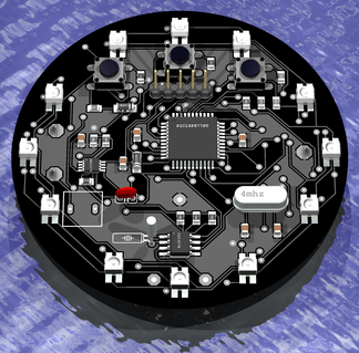
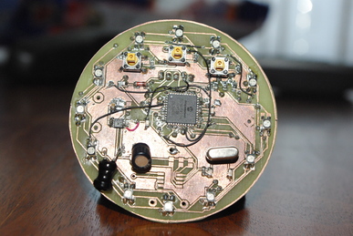
The Image you see above is a 3D rendering of the latest design of the PCB. The rendering is pretty much true to what I expect to build except for a missing inductor and the wrong capacitor in the PSU, which can be seen along with more details in the photo of the prototype after the jump.
The clock contains three basic subsystems; the power supply, microcontroller and finally the real time clock. The power supply draws its current from a single AA battery and uses a boost switching mode power supply to increase the output voltage from the 1.5V provided by the battery to an ample 5V that is used by the microcontroller. The advantage of this type of power supply is that it can operate at very low voltages, down to near 0.7V which allows you to power the clock from AA batteries that other devices may consider to be already dead. In order to conserve power, the clock will not always be displaying the time; after about a minute or so of display, the microcontroller will enter sleep mode and deactivate the power supply. When the user pushes the middle button, it will awaken and display the time for another minute. As an alternative to the AA battery, you can solder a short USB cable that will allow the display to be powered continuously.
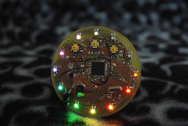
The PIC16F877A microcontroller is the brains behind the clock. The main responsibility of the PIC is to interface to the real time clock and drive the RGB leds. The LEDs each have four connections; a common anode and a cathode for red, green, and blue. The way the LEDs are multiplexed, each LED has its own anode that is connected to an output pin on the PIC. The cathodes are then all tied together and connected through current limiting resistors to three more output pins. The PIC controls the display by selecting an LED by pulling its anode high and then sending three pulse width modulated signals to the RGB cathodes. By carefully choosing the duty cycle of the PWM signals, virtually any colour can be displayed.
The Real Time Clock is the time keeper for the clock. It has its own independant 32.768kHz crystal that is divided and useed to accurately keep track of time. It also has its own CR2032 3V lithium backup battery that is used to keep the time while the main power is not available.
With this clock design, each hand of the clock (hours, minutes, and secconds) will be assigned a colour. The face of the clock will display each hand and as the hands gradually overlap, it will mix the colours to display the time. The second and minute hands will also adjust their brightness between two LEDs on the clock to proportionately display the time when it is in between positions.
Now that you are a familiarized with the general idea of my project, I’ll get into some details on the propsed soldering workshop. For the workshop, participants would be given their very own kit of components, solder, PCB, and battery. The workshop would start with a presentation where I go over the basic anatomy and design of the clock, and discuss the schematic and PCB.
Next, participants will be guided step-by-step through the procedure required to solder each of the components on the board, using several techniques along the way. We will have to find enough fine-tipped soldering irons for everybody to use. As the boards are assembled, we will test independant subsystems with a multimeter and visual inspection. Experienced solderers will be on hand to assist with people who may have trouble with some of the smaller components.
Half-way through, we will break for pizza or subway lunch and return to the workshop in the afternoon. Once the boards are assembled, we will begin programming the boards with pre-written source code. The code will be made available and discussed during the process. This time will also be used to troubleshoot and repair any boards that are not working.
Once the boards are assembled and working, the floor will be opened for questions, ideas, and suggestions for future projects or improvements to this one.
As for cost, currently I have priced out the projects to be approximately $35 per unit, but I expect this to go down a bit if/when I find a cheaper source for a couple of the more expensive components. At this price point, I would suggest that the cost for umIEEE members would be around $20 – $25 and for non-members $30 – $35. For members, umIEEE would be expected to sponsor the remainder of the costs which would be $10-$15 per person (including the cost of Lunch). I would expect to host the workshop on two consecutive Saturdays; the first of which will have 10 spots and the second with 15 spots available.
If you have any questions, please email me directly or post your comments to this page.
Hello!
Can you please send me the latest version of source code for desktop clock and if it posible to be translated into .hex code? (to my email)
The project is very interesting and I’d like it to be my graduate project at my university (Faculty of Electrical Engineering and Computer Science).
Thank you very much,
Antun