A little over a year ago, I decided to dive into the 3D printing arena. I love the idea of being able to design and print in 3D plastic, giving me another tool in my maker arsenal.
My initial idea was to build a simple stepper driver board and heater controller board and connect it to my CNC as a new axis that would allow me to print from my CNC machine as well. I went so far as to build both of these boards and managed to get them working, but after some difficulties and a couple blown driver chips (due to incorrectly hooking them up to my CNC controller board) I decided to try and build an actual 3D printer.
There are several main difference between a 3D printer and a traditional CNC. First, each axis of the CNC machine is driven by a relatively high gear ratio leadscrew, whereas most 3D printers are belt driven. This means that the CNC can be much more precise with its motion, but it is typically much slower than a 3D printer. Second, most 3D printers have their own controller which interprets G-code commands and generates the necessary step signals for the motor drivers. In my CNC setup, this is all handled by the computer running either Mach3 or LinuxCNC which interprets the G-code and is programmed with the acceleration/velocity profiles of each axis. The disadvantage here is that it requires a parallel port output and a reasonably high speed machine to be able to send out the step signals fast enough.
I bought a used Prusa Mendel kit (the original i1), which came with suitable stepper motors, a power supply, and an almost fully assembled prusa mendel mechanical kit.
There are many electronics options available for controlling a hobby 3D printer. Arguably the most popular electronics is an Arduino Mega and a special shield called RAMPS which allows you to connect Pololu stepper driver modules as well as heaters, thermistors, and fans. From here, you can program the Arduino with one of several flavours of firmwares that have been written and developed by the community.
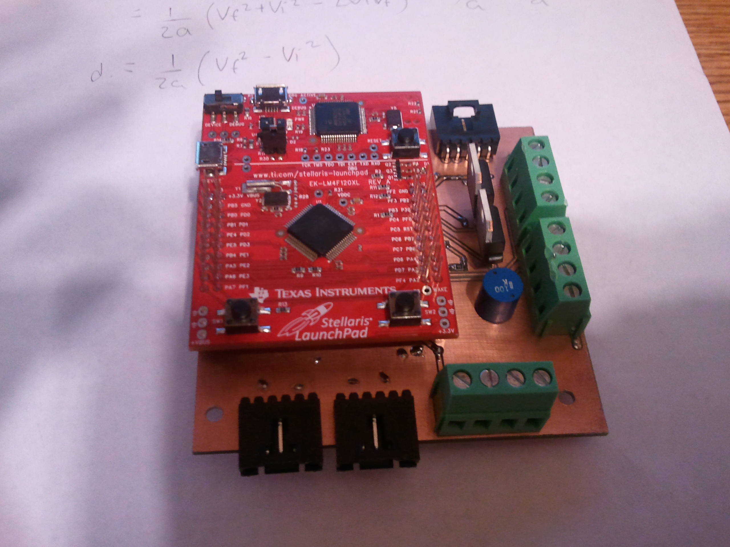
Me, being a bit of a masochist, decided that I would like to build all my own electronics. Having recently acquired a pair of cheap Stellaris Launchpads from Texas Instruments as part of a promotion, I decided to try my hand at using the Stellaris as the brains of my controller and designing my own shield with stepper drivers, heater switches, thermistor inputs, and limit switches. Note that the Stellaris chip has since been renamed as part of the Texas instruments Tiva series, and is now available TM4C123G. This chip is really a pleasure to work with, it is an Arm Cortex-M4 that runs at up to 100MHz with an on-board PLL, and features a floating point unit (FPU), memory management unit (MMU), USB, any a host of other features. The beauty of using an ARM processor is that you can make use of the open-source toolchains available such as the GCC Arm Embedded toolchain. The board also has a built in programmer/debugger that allows you to run and debug programs using GDB.
After testing with a simple stepper driver board, I designed a new stellaris boosterpack (pictured above) that does everything I need. The board has four A4982 stepper driver chips, a pair of power MOSFETs for driving the heaters, three limit switch inputs, and a pair of thermistor analog inputs. I milled the board using my CNC router and assembled it by hand.


- Blank PCB milled with my CNC router.
The schematic of the driver board can be seen here: stepper_schematic.pdf
That’s it for this post, in the next little while I’ll try and post an update showing the board as it is connected to my printer and I’ll discuss in more detail the custom firmware that I’ve written for it.
Pingback: Stellarap Firmware and Hardware | Stellarcore.com
Excellent! waited for that so long )
Thanks! This gives me a great head-start on designing my (mostly) L297/L298-based version. I’m going to use the same pinout on the Launchpad end, so hopefully Stellarap will work “out-of-the-box” (until I start my ham-fisted hacking ;).
Glad that you found it useful! Please let me know if you’d be interested in sharing your design when you’re done. I’d be interested in seeing it and maybe putting it up on here for other to make use of.
Absolutely. In fact, I may write up the whole project and send you a link. I’m currently in the process of designing an extruder around some scavenged parts. I’d like to build the hot-end as well, but I’ll probably just go with a COTS J-head…
BTW, you should post this to the Stellarisiti forum. They have a Booster Pack section:
http://forum.stellarisiti.com/forum/61-stellaristiva-c-launchpad-booster-packs/
Excellent Jobs, THANKS !!!. I will try to build on your work to implement the new tiva c connected launchpad as a base of my 3d printer. – http://www.ti.com/ww/en/launchpad/launchpads-tivac-ek-tm4c1294xl.html#tabs
I always program in ansi c for msp430 family, please advise me if possible.
thanks again!!!
fernando ( reflexpnt)
Hi Fernando,
Since the toolchain uses a standard GCC based compiler, it is definitely possible to compile with forced ANSI compliance by adding a couple of flags (ie -std=C99 and -pedantic).
I don’t believe I have compiled it with those flags, but it shouldn’t be difficult to clean up.
Cheers!
Hi, can i have access to the codes written on the launchpad for the 3D printer you made! i am working on a similar project and it would be a real help !
Hi M. Hadi,
If you take a look at the latest two posts on the Stellarap, you will see that I have included the code at github.
You can access the code here: http://www.github.com/mroy/stellarap
The latest post here: http://www.stellarcore.com/?p=156 includes instructions on how to setup a toolchain and build the firmware.
Best of luck!
I am trying to port your code to Energia. My hardware is a tiva board wired to a CRAMPS board.
I have a few things working. The intepter is processing commands. The heater pwms go on and off. The endstops work. I need help on your stepper isr code. Looks like you are using the timer in one shot mode. Can you explain what’s going on in the isr?
Cool! Please send me a link or something when you’re done, I would love to play around with the resulting port.
As for the stepper control, yes, I am using the one shot mode.
First off, lets just assume one stepper for simplicity. When a move is scheduled by entering a block into the block queue, the timer is scheduled. When the timer goes off, it enters the ISR and looks at the current block in the queue. The ISR will call the step function which turns on the corresponding step/dir pin and increment the counter that keeps track of how far the stepper has moved for the current block. It also checks for endstops to see if the block should be aborted. Since each block has an initial speed, a target speed, and an finish speed, the stepper motor needs to accelerate and decelerate. This is all pre-calculated in the planner, but the ISR will figure out the exact timing of this. At the end of the ISR it will calculate how long it needs to wait until the next interrupt and will re-configure the timer.
It is a little bit more complicated because it is actually controlling four motors at the same time, but the way that it does this is to figure out ahead of time which motor needs to move the farthest and then that motor will be used to determine the overall timing of the block. So, if you are moving in a diagonal line that is mostly X motion, then the timer will be set for the X axis and every time the ISR is entered the X axis should trigger a step while the Y axis might only trigger every third or fourth step, whatever is needed by the move to make sure that the end coordinate is correct.
As I thought it was more complicated. Now I need to see if I can get the oneshot mode to work in Energia. Right now Energia can attachInterrupt() to a change on an I/O pin. I made the timer toggle the RED_LED pin and cause an interrupt. Now I need to dig deeper into the timer spec for tiva.
I have the steppers moving now. I used you stepper interrupt code and the motors moved. You schematic does not match the definitions in your code. I connected the CRAMPS board following your schematic. I fixed that. Now the correct motor moves X, Y Z. Also the endstops stop the correct motor. I am now stuck on getting HOME to work. On G28 command the X motor moves until I hit the endstop. Then the code hangs in a while loop in planner.c.
while (crash->status != BLOCK_ABORTED_RDY && crash->status != BLOCK_COMPLETED); // wait for the machine to reach endstop or finish block.
Glad to hear that you have made some progress! I think that I may have switched around which motor is which on my board since I had them set to different currents. So rather than resoldering some resistors it was easier to just switch them in software.
As for the homing routine, is anything happening while it is in that while loop? The way that the homing routine works is to first move the motor towards the endstop. When it triggers the endstop, it should back off a short distance and then come in again slower. So for each axis it will need to trigger the endstop twice. The while loop that you quoted is specifically waiting for the block to be either complete or aborted by the endstops. If it never reaches one of those two states then I think there may be another problem somewhere else. I would investigate why the block is never completing.
I found the problem; The empty while loops were not working.
while (num_blocks > 0); // wait for finish
I put something in them.
while (num_blocks > 0)
{
digitalWrite(DEBUG_PIN, !digitalRead(DEBUG_PIN));
}; // wait for finish
Home works now!
Now to connect it to printer hardware.
Glad you figured it out. It is likely that the compiler was trying to optimize out the empty loops.