CakePHP Calendar Helper
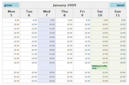
Recently I began my first CakePHP project; for those of you who aren’t aware, CakePHP is a popular model-view-controller framework for creating web applications in PHP. In my project, I had the need for a calendar in a few of my views, and after looking around a bit, I found a nice and simple calendar… Read More »